1 Since I didn't take any disassembly pics, only thinking of photos once reassembly began, this is all in reverse order. Note that there ARE some disassembly hints in here, so a careful read is in order if you're ever planning on doing this. Here's the empty headstock, with things starting to go back together. This task was necessitated by something wrong in the headstock; it was hard to "shift gears". Taking the cover showed a MISSING! shift fork slider. The oil was drained and down in the bottom were PIECES of the missing slider .. and pieces of another smaller slider as well, which I assumed was part of the Fwd/Rev mechanism. Time to disassemble. |
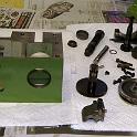
 2 The top pic shows the broken sliders that started this whole project, and the replacements that I fabbed up. I was willing to just pay the price for new ones, but no one had them in stock, so a length of 660 bronze rod was milled to size and drilled as close to center as possible. The holes are amazingly large relative to the width of the slider; small wonder they failed. The bottom pic shows an attempt to use a broken slider by drilling a new hole below the broken one. It didn't really work, though; the whole length of the slider is needed. |
 3 Here's the empty headstock, everything except the Fwd/Rev idler gear removed. I considered running kerosene through it to more thoroughly clean the gunge but in fact a good wipedown with a paper towel was all that was required. |
 4 First step is the Fwd/Rev Leadscrew drive shaft. This was probably the trickiest part, getting the Reverse gear on the shaft because the shifter shaft and slider interfere. Install the shifter shaft and slider first, then work the gear into place; it will just fit. NOTE THE ORIENTATION OF THE GEAR! Then slide in the output shaft and slide the gear onto the shaft, making note of the keyway, while ensuring that the slider stays on the shift shaft and also inside the gear. |
 5 Tighten the two screws on the aluminum endplate, affix the knob/lever to the shift shaft and ensure that it all slides nicely. |
 6 Now slide in the spindle, reinstalling the gears in the order they came out. (You DID pay attention, right?). Then tighten down the aluminum "seal". DISASSEMBLY HINT: Note the black dot on the seal near the screw being installed. The part is not symmetrical, so to make life easier on myself, I marked the 12:00 position. |
 7 Now the rear taper rollers are installed. To get the bearing started, I placed an aluminum tube over the end of the spindle and used it like a slide hammer, going tap tap tap on the bearing until it was 90% of the way seated. Once the bearing is most of the way on, install the spindle nut REVERSED (for now). If you don't, you'll only catch a few threads and risk tearing the threads out. Then tighten down the nut until suitable preload has been applied to the bearings. The manual gives what is, to my mind, an impossible spec. I tightend until it "felt right"; snug, not too snug, with no measurable endplay at all. I'm using a wrench off my ER32 collet closer to do the work at the nut end. DISASSEMBLY HINT: Unless you have another lathe around, you want to make the "slide hammer" tool BEFORE taking things apart! |
 8 At the headstock end, I'm using a 3/8" drive extension. It's not a perfect fit, but it's good enough, as the forces involved are not great. |
 9 Now remove the nut and install the aluminum back plate. Then screw the nut back on the right way until snug and tighten the set screw shown above. DISASSEMBLY NOTE: Don't forget to loosen this screw before unscrewing the nut! |
 10 The gear at the back end of the spindle is clamped to the spindle by a split sleeve. It's purpose is NOT to take up endplay but to ensure that with the Fwd/Rev lever in the neutral position, the leadscrew drive shaft is in fact in neutral. DISASSEMBLY HINT: Don't forget to loosen this! |
 11 Another DISASSEMBLY NOTE: Once the nut was removed, there was the question of how best to push the spindle forward. Since everything is SO WELL MACHINED, it's not a TIGHT fit and a few light taps will probably do. However, that just seems wrong and so I rigged up a puller to push it out. I used some long 6mm allen screws, the existing aluminum cover plate and a centre drilled plug that fit the spindle nicely. HINT1: Make the plug up while the lathe is still functional. HINT2: Instead of using the existing aluminum cover plate, consider making something up out of steel, just in case. You don't want to risk damaging the stock plate. Whatever you use, make sure the bolts/studs are threaded all the way in to grab the maximum amount of thread and also that the plate is perpendicular to the axis of "push". |
 12 Next install the motor drive shaft. Again, you've paid attention to the orientation of the gears, right? Don't forget the shim/spacer; the parts manual shows you where. Ensure that the bearing is all the way in; mine needed a light tap to get it the last 0.100". Of course, no metal on metal contact. I use a 2"x4" block and a LIGHT tap. Again, the precision machining is a real treat as only the lightest of taps was required. |
 13 Don't forget the wavy washer (seen hanging from the shaft) between the bearing and the front side cover. |
 14 Now install the shifter shafts and don't forget the circlips. And don't drop the sliders, it's a pain getting them out again. |
 15 Good common sense is used to adjust the slider arms. I was surprised to find that on the rear arm, I had to compromise a bit on the adjustment. Adjusted so that the gears were fully engaged in the rear position, the gear was only slightly engaged in the forward position (shown here). It seems as if the fork arm is a tiny bit shorter than it should be (IMHO). I compromised so that about 2/3 of the width of the teeth are engaged in both positions, which should be adequate. |
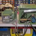
 16 Everything back together, now to install the electrics and see if it still turns! |